
PC1000 Process Controller
The PC1000 process controller is a 19" rack mountable, state-of-the-art, dual loop, dual channel, ramping process controller with many control and monitoring capabilities empowering precise control of factors such as temperature, humidity and pressure. A variety of sensor inputs is available for flexible control. The PC1000 offers local programming via the front panel or remote programming via RS232, RS422 or IEEE-488 interfaces. The PC1000's extensive I/0 capabilities permit maximum flexibility and creativity. An extensive command set assists the user in modelling even the most difficult profile. For those users requiring additional sensors beyond the standard two channels, the optional scanner board may be added to the PC1000 to provide eight more sensor inputs as well as eight open-collector alarm outputs.
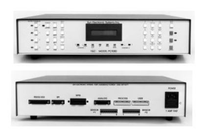 PC1000 front/ back view
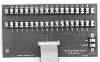 PC1000 Process I/O board
Modes of Operation
The PC1000 can be configured to operate in many ways. In general, the PC1000 can be configured
as a single or dual channel process controller. When used as a single channel controller, channel 2 can be
used to monitor
and also provide limit protection while monitoring. When configured as a dual channel controller,
each channel
can independently control a process.
Some typical applications would be temperature control on channel 1 and monitor on channel 2,
temperature
control on channels 1 and 2 (see application #1), temperature and humidity control (see application
#2) and
temperature and pressure control. The PC1000 is very flexible and will support many control
applications.
Sensor Inputs
Connecting sensors to a process controller can be a cumbersome task, but is simplified with the
PC1000. The PC1000 accepts input from any of the following sources:
RTD, thermocouple, I.C. probe, current and voltage input. The sensors are simply connected to one
of the sensor input ports on the back of the PC1000. The sensor type may then be selected via a
menu in the PC1000. Each channel can be configured independently. Menus are also
present to calibrate the sensors and to select units of measure for each channel. Each channel
may be configured for degrees C, F, K, % relative humidity or user units.
Local and Remote Control
Programming the PC1000 is made easy with the ability to program locally using the front panel and having the flexibility to program remotely using the IEEE-488, RS232 or RS422 busses (all standard on every PC1000). The PC1000 has a BASIC-like command set including FOR-NEXT loops for cycling and GOSUB commands to call other local programs - all features that allow execution of complex temperature profiles. Local programs can be entered by the front panel or uploaded from a host computer.
Process Control
The PC1000 can control a variety of processes and can fit into most applications. The following
features are standard on every PC1000.
• PID Control - The PC1000 has dual PID control for each channel.
• Sensor Inputs - Each input channel is electrically isolated and has 15 bit accuracy as well as the
ability to detect open or shorted probe conditions.
• Cascade Control - This method of PID control blends the probe readings of both channels. For
example, this PID mode would be used when trying to control the temperature of a device under test
while the other channel is controlling the process temperature.
• Staged Control Outputs - Each channel has one staged control output. These outputs enable the
user to control power boost heaters, for example, in addition to the normal heater.
• Guaranteed Soak - This requires that the process is within a specified window of the set point
before the wait (soak) time begins counting down.
• Time of Day Start - This feature allows the user to preset a time of day that the controller will begin
execution of a stored local program.
• Process Limit Alarms - These are alarms that are generated for upper, lower and deviation limits.
All can be enabled or disabled by a menu in the PC1000.
I/O
Bit I/0 to control on/off processes consists of eight 100mA open collector drivers capable
of driving solid state relays. These are easily accessible via the process I/0 board which is
supplied with the PC1000. This is a screw terminal interface card that connects to the PC1000 via a 26 conductor flat cable. Four of the outputs are used for the +/- controls for
channels 1 and 2. One is for power on/off and the remaining three can be used for other control with two of these configurable for staged output use. Also on the process I/0 board is a
contact input for a failsafe as well as 8 additional contact inputs with internal pull up resistors to 5 Volts. The I/0 on the process I/0 board are accessible with IN/OUT commands.
Analog I/O
In addition to the bit I/0, the PC1000 also provides 4 analog outputs and 4 analog inputs. Two of the analog outputs can be configured to drive a chart recorder, for example. The other two analog outputs can be configured for analog process control with the PID loop control being output. The analog output channels can be configured for -5V to +5V or 0V to +5V. One channel can be configured for 0-20mA output. The analog input channels accept input from 0-5V with one channel configurable as a 0-20mA current input. All 4 analog inputs and outputs can also be accessed via input and output commands.
Digital Parallel User I/O
This interface provides the user with 16 bits of address and an 8 bit bidirectional data bus. This provides up to 64K of read/write space to be used for accessories or for the users' custom requirements. The user bus is accessible via IN/OUT commands.
High Speed Serial Link I/O
This is a 56K synchronous serial data link which facilitates distributed microprocessor communications. The PC1000 is configured as a master device and the interface levels conform to RS422 levels. Programming easy and efficient. Below is a sample.
Applications
Example #1: Temperature - Temperature
The first application presented is control of a temperature-temperature process. It is first necessary
to put the PC1000 in the dual loop control mode. This is accomplished by accessing the SDEF
menu via the front panel.
After answering "YES" to the "DUAL LOOP CONTROL" prompt, the PC1000 can control two
processes. Next, the sensors to be used must be calibrated. This is done by accessing the CAL
menu from the front panel. There are many different sensors to choose from and the CAL menu will
prompt for the appropriate inputs to reliably calibrate the sensors. Once the above has been
completed, the following profile can be achieved using the program and the schematic shown.

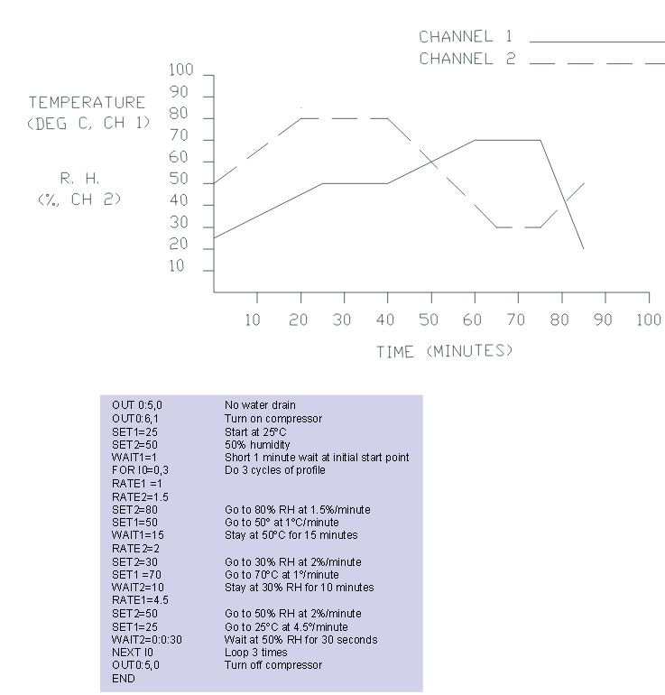
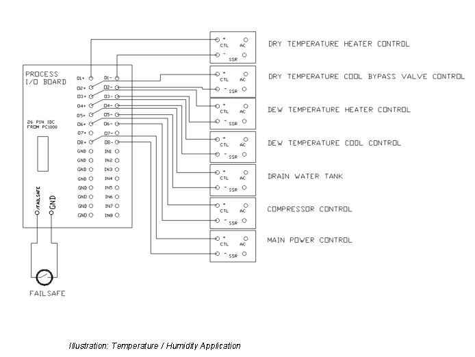
Example #2: Temperature-Humidity
This application deals with the control of temperature and humidity using the dry/dew point method.
This method is based on the fact that given a particular dry temperature and humidity, a unique dew
point can be calculated from a psychometric table. Dew point is defined as the temperature at
which the air is saturated or 100% relative humidity. lf the saturated air at the dewpoint temperature
is then heated to the dry temperature, the desired relative humidity is achieved.
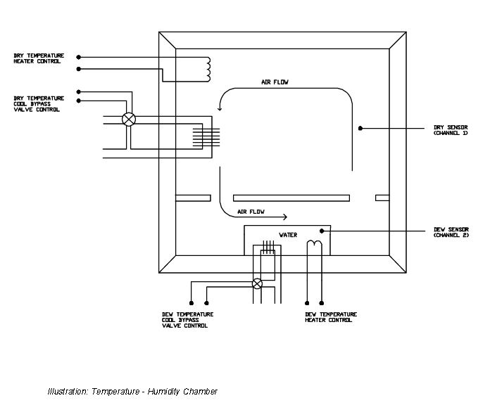
Based on this, the diagram of the chamber can be fully explained. As air slowly passes over the
bath of water, that air becomes saturated at the temperature of the bath of water. The temperature
of this bath of water is maintained at the dew point temperature associated with the dry temperature
and relative humidity desired. This saturated air at the dewpoint temperature then flows up into the
top part of the chamber where it is heated to the dry temperature and at the same time establishing
the proper relative humidity. The PC1000 controls the dry and dew temperatures based on the
values entered for temperature and humidity. Channel 1 outputs must control the dry temperature
and channel 1 sensor must be sensing the dry temperature. Channel 2 outputs must control the
dew temperature and the channel 2 sensor must be sensing the bath of water. When entering set
points, channel 1 set point is the dry temperature and channel 2 is the RH. The dew point is
calculated by the PC1000 and it is this temperature that the PC1000 controls.
Since it is desired to control the temperature and humidity, the PC1000 must be in the dual loop
mode. This is accomplished by accessing the SDEF menu. The PC1000, still in the SDEF menu,
will then ask if auto-RH is desired on channel 2. After responding "YES" to this prompt, the dew
mode would then be selected when prompted next. (The other option which could be used to
calculate relative humidity is wet bulb.)
After setting up the PC1000 in the previously described manner, and making the proper connections
from the process I/0 board, as shown, the desired profile is easily accomplished. The following local
program could be downloaded from a host computer or entered locally via the front panel keypad.
- Power Consumption: 35 Watts
Input Voltage: 110/220 +- 10% (selectable at rear panel)
Line Frequency: 50/60 Hz
Dimensions: 3.5" (H) x 16.5" (W) x 15" (D) - 19" rack mountable
Front Panel: 32 key, 16 x 2 line LCD
Rear Panel: Contains all I/O ports
Sensor Malfunction: Open/Short probe detect
Controller Malfunction: Hardware watch dog
Process Errors: External Failsafe Input
Process Limits: Upper, Lower and process deviation limits
Line Voltage loss: Battery-Backed memory & time of day clock, auto restart after power loss - SENSORS ACCEPTED:
- RTD (.385 or .392): -200C to +325C
J thermocouple: -200C to +760C
K thermocouple: -200C to +1250C
T thermocouple: -200C to +325C
Solid State: -60C to +160C
Voltage: 0 to 5 Volt
Current: 0 to 20 mA - Resolution: 15 bit conversion
- Absolute Error Over Range (not including probe error):
- RTD: +- .2C
J/K narrow: +- .35C
J/K wide: +- .5C
Voltage: +- 500 uV
Current: +- 2uA
Electrical Isolation: 240VAC